Elevator Communications Failure
ASME A17.1-2019 / CSA B44-19 Safety Code for Elevators and Escalators
ASME A17.1-2019 / CSA B44-19 ‘Safety Code for Elevators and Escalators‘

Section 2.13: Power Operation of Hoistway Doors and Car Doors
- 2.13.5 Reopening Device(s) for Power-Operated Horizontally Sliding Doors and Gates
Reopening device(s) for power-operated horizontally sliding doors or gates shall conform to the requirements of 2.13.5.1 through 2.13.5.6. Where the term “door(s)” is used, the requirement shall apply to “gate(s)” as well.
- 2.13.5.1 Where Required and Function.
Where required by 2.13.4, power-operated doors shall be provided with a reopening device(s) that operates as follows:- a) If an object has been detected in accordance with 2.13.5.3 or 2.13.5.4 when the doors are fully open, the hoistway door and car door shall not close or, when the doors are closing, the car door and hoistway door at the landing shall initiate a reversal without intentional delay beyond system response time, and shall fully reopen or reopen a minimum of 915 mm (36 in.).
- b) If the doors fail to fully close [see 2.12.2.2(a)] within 10 s in addition to the door close data plate value, the doors shall fully reopen.
- 2.13.5.2 Rendering Inoperative
- a) The reopening device(s) shall be permitted to be rendered inoperative
- 1) when the closing kinetic energy is reduced in accordance with 2.13.4.2.1(c)(1) and 2.13.4.2.1(c)(2)
- 2) for detection of approaching objects
- a) within 450 mm (18 in.) of the point at which the leading edge of the leading door panel contacts the door jamb or opposing door panel.
- b) when 20 s have transpired after the detection means of approaching objects first detects an object. When an object is detected in the path of the doors, the 20 s duration shall reset.
- 3) for detection of objects in the door path, within 20 mm (0.75 in.) of the point at which the leading edge of the leading door panel contacts the door jamb or opposing door panel
- b) Where Phase I Emergency Recall Operation by a fire alarm initiating device (see 2.27.3.2) is not provided, door reopening devices that can be affected by smoke or flame shall be rendered inoperative after the doors have been held open for 20 s after a door close signal has been initiated. Door closing for power-operated doors shall conform to 2.13.4.
- c) When the reopening device(s) has been rendered inoperative per (a)(1), a continuously sounding audible signal shall be provided with a sound level of 10 dBA minimum above ambient and shall not exceed 80 dBA. The sound level shall be measured 1 m 40 in.) above the landing floor, 500 mm (20 in.) from the door face, along the centerline of the entrance opening, with the doors open. The signal shall sound during door closing until the doors are fully closed. In no case shall the sound level exceed 85 dBA inside the cab and within 300 mm (12 in.) from the centerline of the entrance and 1 m (40 in.) above the floor.
- a) The reopening device(s) shall be permitted to be rendered inoperative
- 2.13.5.3 Detection of Approaching Objects.
The reopening device(s) shall be designed to detect a cylindrical target(s) approaching the entrance opening of the landing-side doors as required by 2.13.5.3.1. The cylindrical target(s) shall be oriented with the base parallel to the floor, the height perpendicular to the floor, and properties conforming to the following:- a) diameter of 200 mm (8 in.), height of 1 000 mm (40 in.), and painted flat black per FED-STD-595C in the color range from 37005 through 37050 diameter of 200 mm (8 in.), height of 1 000 mm (40 in.), and painted glossy white per FED-STD-595C in the color range from 17800 through 17999 NOTE (2.13.5.3): See Nonmandatory Appendix S, Figure S-13.
- 2.13.5.3.1 Each cylindrical target shall be moved toward the entrance, perpendicular to the plane of the landing door, at any speed up to 1 m/s (3 ft/s). The cylindrical target shall be detected while moving toward the entrance anywhere between 500 mm (20 in.) and 225 mm (9 in.) from the landing-side face of the hoistway door and 225 mm (9 in.) ahead of the leading edge (see Nonmandatory Appendix S, Figure S-16 for moving line of detection). The cylindrical target shall be permitted to be detected prior to the position defined above. The approaching object detection means shall be effective until the leading edge of the doors is within 450 mm (18 in.) of the fully closed position and shall be permitted to be effective up to the fully closed position.
- 2.13.5.4 Detection of Objects in the Door Path.
The reopening device(s) shall be designed to detect rectangular prisms positioned as required by 2.13.5.4.1 and 2.13.5.4.2 with properties conforming to the following:- a) 80 mm (3.15 in.) by 50 mm (2 in.) by 150 mm (6 in.), painted flat black per FED-STD-595C in the color range from 37005 through 37050
- b) 80 mm (3.15 in.) by 50 mm (2 in.) by 150 mm (6 in.), painted glossy white per FED-STD-595C in the color range from 17800 through 17999 NOTE (2.13.5.4): See Nonmandatory Appendix S, Figures S-14 and S-15.
- 2.13.5.4.1 The device(s) shall be designed to detect prisms positioned anywhere within the opening width of the entrance vertically between two horizontal planes located 25 mm (1 in.) and 1 525 mm (60 in.), respectively, above the floor and oriented with the 50 mm (2 in.) dimension parallel to the floor, the 150 mm (6 in.) dimension perpendicular to the door, and the 80 mm (3.15 in.) dimension perpendicular to the floor
- a) wholly located between the vertical planes established by the landing-side face of the hoistway door and the car-side face of the car door or
- b) centered between the two vertical planes described in (a) if the distance between the two planes is less than 150 mm (6 in.)
- 2.13.5.4.2 The device(s) shall be designed to detect prisms positioned anywhere within the opening width of the entrance on the floor and oriented with the 80 mm (3.15 in.) dimension parallel to the floor, the 150 mm (6 in.) dimension perpendicular to the door, and the 50 mm (2 in.) dimension perpendicular to the floor
- a) wholly located between the vertical planes established by the landing-side face of the hoistway door and the car-side face of the car door or
- b) centered between the two planes if the distance between the two planes is less than 150 mm (6 in.)
- 2.13.5.5 Self-Monitoring of Detection Means.
The system shall be designed to be self-monitoring. After the door has reached its fully opened position and before door closing is initiated, the detection means shall be self-checked to verify the detection means is operational. If the self-check outcome is unsuccessful, power closing of the door(s) shall be at reduced kinetic energy conforming to 2.13.4.2.1(c)(2).
Section 2.27.1: Car Emergency Signaling Devices
- 2.27.1 Car Emergency Signaling Devices
- 2.27.1.1 Emergency Communications. The two-way communications shall conform to 2.27.1.1.1 through 2.27.1.1.6.
- 2.27.1.1.1 A communications means between the car and a location staffed by authorized personnel who can take appropriate action shall be provided.
- 2.27.1.1.2 If the call is not acknowledged [2.27.1.1.3(c)] within 45 s, the call shall be automatically directed to an alternate on- or off-site location.
- 2.27.1.1.3 The communications means within the car shall comply with the following requirements:
- (a) In jurisdictions enforcing the NBCC, Nonmandatory Appendix E; in jurisdictions not enforcing the NBCC, ANSI/ICC A117.1, ADAAG, or ADA/ABAAG.
- (b) A push button to actuate the communications means shall be provided in or adjacent to a car operating panel. The push button shall be visible and permanently identified with the phone symbol (see 2.26.12.1). The identification shall be on or adjacent to the phone push button. The communications means shall be initiated when the push button is actuated.
- (c) On the same panel as the phone push button, a message shall be displayed that is activated by authorized personnel to acknowledge that communications are established. The message shall be permitted to be extinguished where necessary to display a new message [see (d) and (e)] or when the communications are terminated.
- (d) On the same panel as the phone push button, messages shall be displayed that permit authorized personnel to communicate with and obtain responses from a trapped passenger(s), including a passenger(s) who cannot verbally communicate or hear.
- (e) On the same panel as the phone push button, a message shall be displayed that is activated by the authorized personnel to indicate when help is on the way. The message shall continue to be displayed until a new message is displayed [see 2.27.1.1.4(c)] or the communications are terminated.
- (f) The communications means shall provide on demand to authorized personnel information that identifies the building location and elevator number.
- (g) The communications, once established, shall be disconnected only when authorized personnel terminate the call or a timed termination occurs. A timed termination by the communications means in the elevator, with the ability to extend the call by authorized personnel, is permitted if voice notification is sent by the communications means to authorized personnel a minimum of 3 min after communication has been established. Upon notification, authorized personnel shall have the ability to extend the call; automatic disconnection shall be permitted if the means to extend are not enacted within 20 s of the voice notification.
- (h) The communications means shall not use a handset in the car.
- (i) The communications shall not be transmitted to an automated answering system. The call shall be answered by authorized personnel.
- (j) Operating instructions shall be incorporated with or adjacent to the phone push button.
- (k) A means to display video to observe passengers at any location on the car floor, to authorized personnel for entrapment assessment, shall be provided.
- 2.27.1.1.4 Where the elevator rise is 18 m (60 ft) or more, a communications means within the building accessible to emergency personnel shall be provided and shall comply with the following requirements:
- (a) The means shall enable emergency personnel within the building to establish communications to each car individually. The communications shall be established without any intentional delay and shall not require intervention by a person within the car. The means shall override voice communications to outside of the building.
- (b) The communications, once established, shall be disconnected only when emergency personnel terminate the call or a timed termination occurs. A timed termination by the communications means in the elevator, with the ability to extend the call by emergency personnel, is permitted if voice notification is sent by the communications means to emergency personnel a minimum of 3 min after communication has been established. Upon notification, emergency personnel shall have the ability to extend the call; automatic disconnection shall be permitted if the means to extend are not enacted within 20 s of the voice notification.
- (c) Once the communications have been established, a message shall be displayed on the same panel as the phone push button, that is activated by emergency personnel to indicate that help is on-site. The message shall be permitted to be extinguished where necessary to display a new message [see (e)] or when the communications are terminated.
- (d) Operating instructions shall be incorporated with or adjacent to the communications means outside the car. Instructions shall conform to 2.27.7.3.
- (e) On the same panel as the phone push button, messages shall be displayed that permit emergency personnel to communicate with and obtain responses from a trapped passenger, including a passenger who cannot verbally communicate or hear.
- (f) A means to display video to observe passengers at any location on the car floor, to emergency personnel for entrapment assessment, shall be provided.
- 2.27.1.1.5 If the communications means is connected to the normal building power, it shall automatically transfer to an auxiliary power supply as required by the applicable building code or, where applicable, NFPA 99, after the normal building power fails. This power source(s) shall be capable of providing for the means of communications (see 2.27.1.1.3 a n d 2.27.1.1.4) for at least 4h and the audible signaling device (see 2.27.1.2) for at least 1h.
- 2.27.1.1.6
- (a) The voice communication means within the car shall include a means to verify operability of the telephone line, where
- (1) verification of the telephone line operability shall be automatically performed
- (2) verification may be continuous or periodic
- (3) periodic verification shall be at least on a daily basis
- (4) verification shall not require activation of the communications link(s) If means other than a telephone line (e.g., VOIP, network, intercom) are used for the communications, similar verification of this equivalent means shall be performed.
- (a) The voice communication means within the car shall include a means to verify operability of the telephone line, where
- 2.27.1.2 Emergency Stop Switch Audible Signal.
When an emergency stop switch (2.26.2.5) is provided, an audible signaling device shall be provided. The audible signaling device shall:- (a) have a rated sound pressure rating of not less than 80 dBA nor greater than 90 dBA at 3 m (10 ft)
- (b) respond without delay after the switch has been activated
- (c) be located inside the building and audible inside the car and outside the hoistway
- (d) for elevators with a rise greater than 30 m (100 ft), be duplicated as follows:
- (1) one device shall be mounted on the car
- (2) a second device shall be placed at the designated level
Products
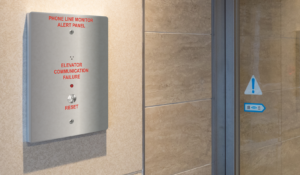
2100-ALARM After Market System
The 2100-ALARM provides a simple, fully functional solution to meet the 2010 and 2013 ASME codes. The code states that each elevator phone needs to check for an active phone line at least once in a 24 hour period.
The 2100-ALARM checks the complete phone line system from the elevators to the machine room, and from the machine room to the outside world
If an active phone line is not detected, an audible and visual alarm at the main landing panel is activated
A key switch is used to silence the audible alarm
If the phone line has not been re-established within a 24 hour period, the audible will resound

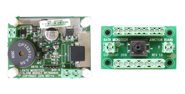
OEM System – Alarm and Junction Board
The OEM System – Alarm and Junction Board provides a simple, fully functional solution to meet the 2010 and 2013 ASME codes. The code states that each elevator phone needs to check for an active phone line at least once in a 24 hour period.
The OEM System – Alarm and Junction Board checks the complete phone line system from the elevators to the machine room, and from the machine room to the outside world
If an active phone line is not detected, an audible and visual alarm at the main landing panel is activated
A key switch is used to silence the audible alarm
If the phone line has not been re-established within a 24 hour period, the audible will resound
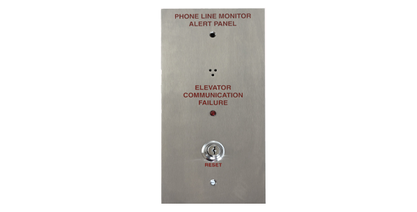
LMA Line Monitoring Alert
Designed to work with our EMS phones. The Phone Line Monitoring Alert Panel meets the ASME / B44 2009 and 2010 code that requires audible and visual signal in the lobby in the event of phone line failure.
When used with our phones, that have the phone line monitoring option, the LMA unit completes the system.
The 2100-ALARM checks the complete phone line system from the elevators to the machine room, and from the machine room to the outside world
If an active phone line is not detected, an audible and visual alarm at the main landing panel is activated
Reset allows audible signal to be silenced with standard J200 key
Resets automatically when phone line is restored

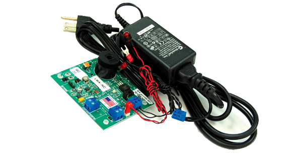
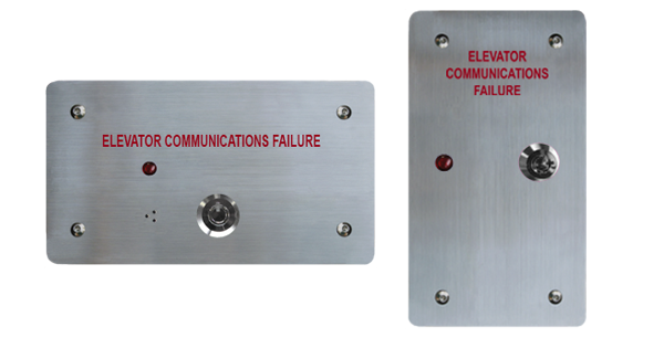
LMA-NC Line Monitoring Alert No Cover
The Phone Line Monitoring Alert Kit meets the ASME / B44 2009 and 2010 code that requires audible and visual signal in the lobby in the event of phone line failure.
When used with our EMS phones, that have the phone line monitoring option, the LMA-NC unit completes the system.
The OEM system checks the complete phone line system from the elevators to the machine room, and from the machine room to the outside world
If an active phone line is not detected, an audible and visual alarm at the main landing panel is activated
Reset allows audible signal to be silenced with standard J200 key
Resets automatically when phone line is restored

LMX Line Monitoring Expansion
If more than one elevator phone needs to be linked to the LMA panel, an LMX (Line Monitoring Expansion) unit can be mounted in the machine room which will allow up to ten elevator phones to be connected
Provides unlimited expansion when using multiple LMX units
Includes optically isolated interface to protect all phones and LMA panel
Cost effective solution to interface multiple phones to LMA panel
Provides unlimited expansion when using multiple LMX units
Includes optically isolated interface to protect all phones and LMA panel
Cost effective solution to interface multiple phones to LMA panel