Elevator Light Curtains

More than 2 million AVIRE light curtains have reached customers ranging from global elevator manufacturers to local installers.

Main products

Lift Light Curtains Panachrome
The MEMCO Panachrome lift detector is ideal for high-traffic areas, e.g., hospitals, hotels, or airports. Patented red/green LED lights warn when the doors are closing, and sensors detect lift door blockage. Optional 3D sensors extend protection into the landing area.
Lift Light Curtains Panachrome+
The MEMCO Panachrome+ lift curtain with red and green LEDs highlights door movements, making lifts safer and reducing accidents. 3D detection extends passenger protection into the landing zone, and remote diagnostics reduce site visit frequency.
Lift Light Curtains Smart 3D
The MEMCO Smart 3D lift detector for Panachrome+ lift curtains is an innovative product that resolves common problems with 3D edges technology, reducing the false triggers caused by reflected light or flooring, stationary objects, dark clothing, and cross traffic.
Lift Light Curtains Pana 40+
The MEMCO Pana 40+ is our bestselling lift light curtain. Suitable for any installation, due to the range of available profiles. The exceptional quality, reliability, and durability make it perfect for high-risk and high-traffic applications.
Lift Light Curtains E-Series
The E-Series Lift Light Curtains is our entry-level lift door detector that fulfills all basic compliance requirements. It is easily and quickly integrated into door leading edges of existing or new lifts to prevent passenger accidents and door damage.

Elevator Light Curtains
standards

EN 81-20

EN 81-20

EN 81-20 Standards for Lift Light Curtains

The EN 81-20 lift safety standards provide minimum safety requirements for passenger and goods lifts. We provide a clear and comprehensive overview of the lift safety requirements, particularly the standards for lift light curtains.  

Why was EN 81-20 needed to regulate lift safety requirements? 

The lift safety standard was introduced to increase safety due to changes in proven technology, and bring the requirements in line with modified EU directives. It also eliminated the separate standards for hydraulic lifts and introduced the requirement for risk analysis and compliance. 

Some of the issues the new standard aimed to address include increased strength of doors, car, and well, improved lighting in the lift car, stopping people being able to exit the car if it stopped between floors, improved materials such as flameproof materials and safety glass, increased refuge space, increased refugee space in the pit and more headroom, and improvements to the lift doors and lift light curtains to protect passengers from injury when the lift door closes.  

EN 81-20 lift safety requirements  

The EN 81-20 safety requirements were introduced in 2017 and apply to all new lifts. They cover all aspects of lift safety, including lighting, material strength, flameproofing, and refuge space.  

The EN 81 series covers different aspects of lift safety. EN 81-20 is the overarching standard, covering safety rules for the construction and installation of lifts that transport people and goods. The rest of the EN 81 series covers specific safety measures, such as the standards for remote alarms on passenger and goods lifts (EN 81-28) and accessibility standards, including for persons with a disability (EN 81-70).  

Section 5.3.6.2.1.1 of EN 81-20 contains the regulations that set lift light curtains standards.  

5.3.6.2.1.1 Automatic power-operated doors 

The following applies: 

  1. The kinetic energy of the landing and / or car door and the mechanical elements which are rigidly connected to it, calculated or measured at the average closing speed shall not exceed 10J. 

The average closing speed of a sliding door is calculated over its whole travel, less: 

  • 25mm at each end of the travel in the case of centrally-closing doors; 
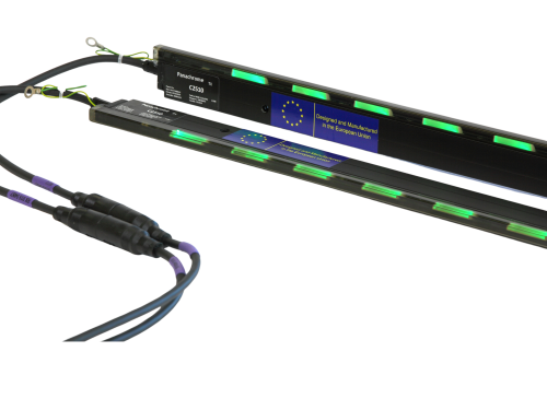
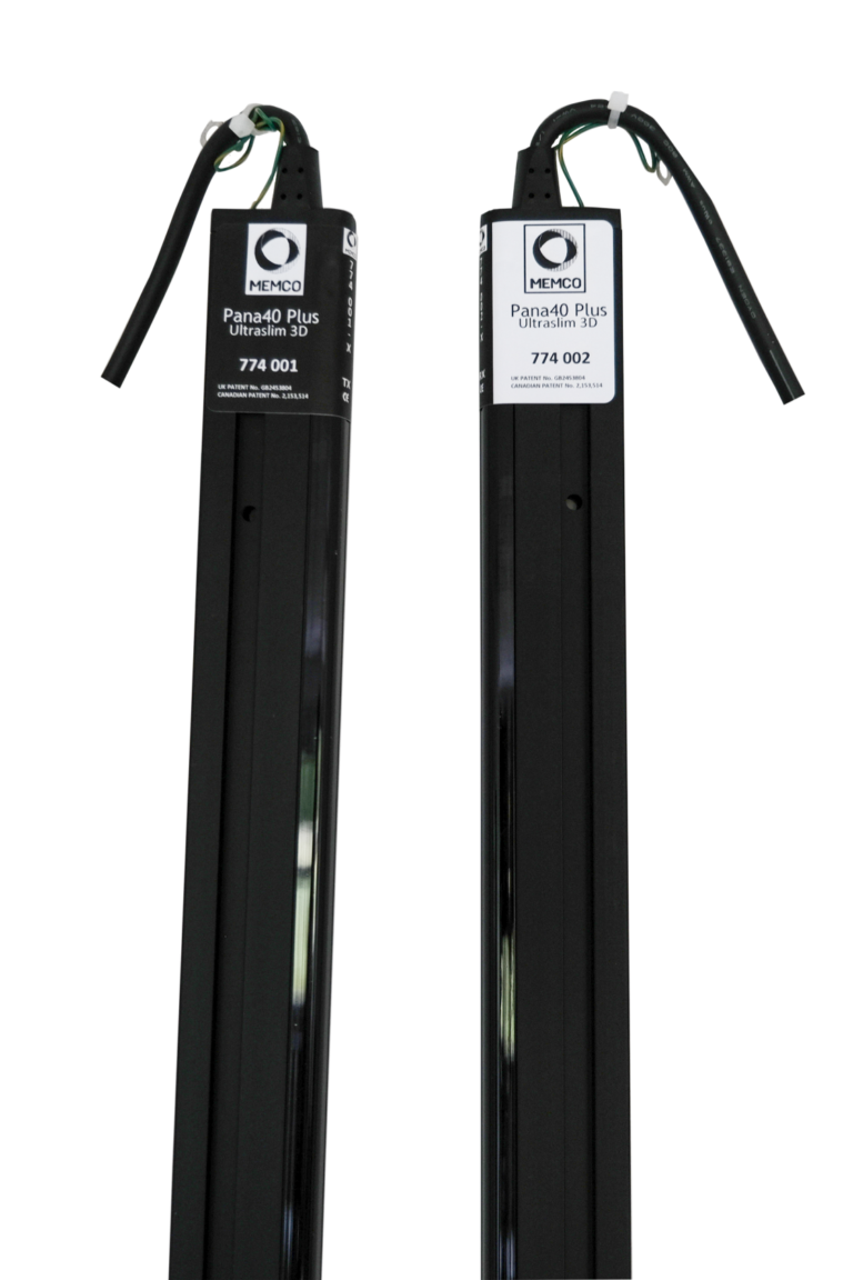
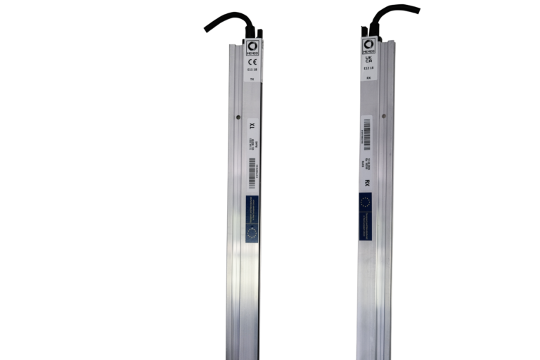
  • The door detector must detect obstacles as small as 50 mm in diameter. To provide this protection from 25 mm to 1600 mm, the door edge needs a minimum of 36 diodes arranged vertically. 

A protective device shall automatically initiate reopening of the door(s) in the event of a person crossing the entrance during the closing movement. The protective device may be rendered inoperative in the last 20mm of door closing or gap. 

What are the EN 81-20 standards for lift light curtains? 

The EN 81-20 lift standards provide minimum safety requirements for the lift door mechanism on passenger and goods lifts. 

Distance above the car door sill  

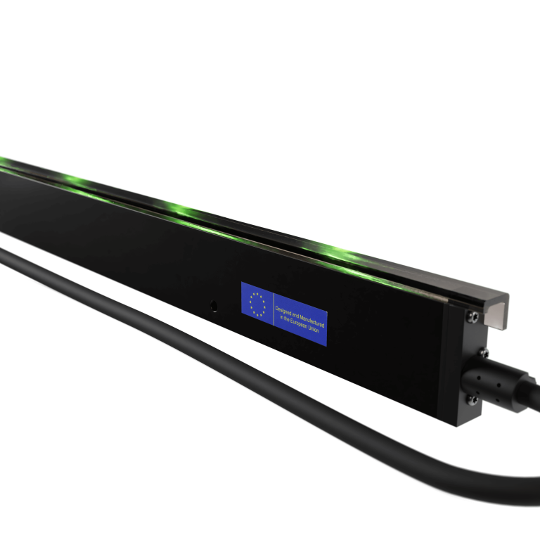
The protective device (e.g., the lift light curtain) shall cover the opening over the distance between at least 25mm and 1600mm above the car door sill. 

Minimum size of objects to be detected by lift light curtains  

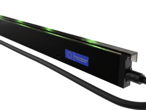
Lift light curtains – also known as detectors or safety edges – are safety devices made up of infrared beams to detect the presence of a person or object in the doors’ path. Standard light curtains have 36 of these beams, or diodes. The EN 81-20 standard ensures that the lift light curtain will detect an object of 50mm, which is the diameter of a child’s lift. This reduces the risk of injury to passengers and damage to the lift.  

Obstruction or damage to lift light curtains leading to non-compliance with EN 81-20 

When the infrared beams are blocked or damaged – for instance, when a sticker is placed over them, corrosive cleaning materials are used, or an object is placed between the doors to stop them closing – the light curtain may no longer comply with EN 81-20 regulations.  

Limitation of the kinetic energy of doors  

If a failure occurs, or the door detector is deactivated, EN 81-20 requires the kinetic energy of the doors to be limited to 4J, and an acoustic signal to be operated as the doors closed. A diagnostic tool in the door’s detector unit can communicate this safety system failure.  

The EN 81-20 lift standards and requirements for lift light curtains in older lifts  

While the EN 81-20 lift standards do not apply to older lifts, the industry has adopted these safety standards to increase safety and reduce lift damage. Property owners who upgrade their lift safety systems to meet the new requirements will increase the value of their property while increasing passenger safety.  

How to ensure your building meets EN 81-20 lift safety requirements  

It can be challenging to keep track of changes to lift safety requirements. That’s why our mechanics and engineers are trained comprehensively on all safety standards, and can help plan lifts for a new property or upgrade existing lifts to be fully compliant with EN 81-20.  

Going beyond the minimum safety requirements of EN 81-20 

All MEMCO products comply with EN 81-20 regulations, and many of our solutions go well beyond the minimum safety requirements. 

For example, the leading cause of lift failure is door damage caused by someone inserting an object between the doors to stop them from closing. A more advanced lift light curtain can alert the lift owner to obstructions or damage that may cause non-compliance with lift safety legislation. 

Digital lift monitoring solutions via the AVIRE Hub make it easy to comply with monitoring requirements and the 3-day test calls.  

ASME A17.1-2019 / CSA B44-19 Safety Code for Elevators and Escalators

ASME A17.1-2019 / CSA B44-19 ‘Safety Code for Elevators and Escalators

Section 2.13: Power Operation of Hoistway Doors and Car Doors

  • 2.13.5 Reopening Device(s) for Power-Operated Horizontally Sliding Doors and Gates
    Reopening device(s) for power-operated horizontally sliding doors or gates shall conform to the requirements of 2.13.5.1 through 2.13.5.6. Where the term “door(s)” is used, the requirement shall apply to “gate(s)” as well.
  • 2.13.5.1 Where Required and Function.
    Where required by 2.13.4, power-operated doors shall be provided with a reopening device(s) that operates as follows:
    • a) If an object has been detected in accordance with 2.13.5.3 or 2.13.5.4 when the doors are fully open, the hoistway door and car door shall not close or, when the doors are closing, the car door and hoistway door at the landing shall initiate a reversal without intentional delay beyond system response time, and shall fully reopen or reopen a minimum of 915 mm (36 in.).
    • b) If the doors fail to fully close [see 2.12.2.2(a)] within 10 s in addition to the door close data plate value, the doors shall fully reopen.
  • 2.13.5.2 Rendering Inoperative
    • a) The reopening device(s) shall be permitted to be rendered inoperative
      • 1) when the closing kinetic energy is reduced in accordance with 2.13.4.2.1(c)(1) and 2.13.4.2.1(c)(2)
      • 2) for detection of approaching objects
        • a) within 450 mm (18 in.) of the point at which the leading edge of the leading door panel contacts the door jamb or opposing door panel.
        • b) when 20 s have transpired after the detection means of approaching objects first detects an object. When an object is detected in the path of the doors, the 20 s duration shall reset.
      • 3) for detection of objects in the door path, within 20 mm (0.75 in.) of the point at which the leading edge of the leading door panel contacts the door jamb or opposing door panel
    • b) Where Phase I Emergency Recall Operation by a fire alarm initiating device (see 2.27.3.2) is not provided, door reopening devices that can be affected by smoke or flame shall be rendered inoperative after the doors have been held open for 20 s after a door close signal has been initiated. Door closing for power-operated doors shall conform to 2.13.4.
    • c) When the reopening device(s) has been rendered inoperative per (a)(1), a continuously sounding audible signal shall be provided with a sound level of 10 dBA minimum above ambient and shall not exceed 80 dBA. The sound level shall be measured 1 m 40 in.) above the landing floor, 500 mm (20 in.) from the door face, along the centerline of the entrance opening, with the doors open. The signal shall sound during door closing until the doors are fully closed. In no case shall the sound level exceed 85 dBA inside the cab and within 300 mm (12 in.) from the centerline of the entrance and 1 m (40 in.) above the floor.
  • 2.13.5.3 Detection of Approaching Objects.
    The reopening device(s) shall be designed to detect a cylindrical target(s) approaching the entrance opening of the landing-side doors as required by 2.13.5.3.1. The cylindrical target(s) shall be oriented with the base parallel to the floor, the height perpendicular to the floor, and properties conforming to the following:
    • a) diameter of 200 mm (8 in.), height of 1 000 mm (40 in.), and painted flat black per FED-STD-595C in the color range from 37005 through 37050 diameter of 200 mm (8 in.), height of 1 000 mm (40 in.), and painted glossy white per FED-STD-595C in the color range from 17800 through 17999 NOTE (2.13.5.3): See Nonmandatory Appendix S, Figure S-13.
  • 2.13.5.3.1 Each cylindrical target shall be moved toward the entrance, perpendicular to the plane of the landing door, at any speed up to 1 m/s (3 ft/s). The cylindrical target shall be detected while moving toward the entrance anywhere between 500 mm (20 in.) and 225 mm (9 in.) from the landing-side face of the hoistway door and 225 mm (9 in.) ahead of the leading edge (see Nonmandatory Appendix S, Figure S-16 for moving line of detection). The cylindrical target shall be permitted to be detected prior to the position defined above. The approaching object detection means shall be effective until the leading edge of the doors is within 450 mm (18 in.) of the fully closed position and shall be permitted to be effective up to the fully closed position.
  • 2.13.5.4 Detection of Objects in the Door Path.
    The reopening device(s) shall be designed to detect rectangular prisms positioned as required by 2.13.5.4.1 and 2.13.5.4.2 with properties conforming to the following:
    • a) 80 mm (3.15 in.) by 50 mm (2 in.) by 150 mm (6 in.), painted flat black per FED-STD-595C in the color range from 37005 through 37050
    • b) 80 mm (3.15 in.) by 50 mm (2 in.) by 150 mm (6 in.), painted glossy white per FED-STD-595C in the color range from 17800 through 17999 NOTE (2.13.5.4): See Nonmandatory Appendix S, Figures S-14 and S-15.
  • 2.13.5.4.1 The device(s) shall be designed to detect prisms positioned anywhere within the opening width of the entrance vertically between two horizontal planes located 25 mm (1 in.) and 1 525 mm (60 in.), respectively, above the floor and oriented with the 50 mm (2 in.) dimension parallel to the floor, the 150 mm (6 in.) dimension perpendicular to the door, and the 80 mm (3.15 in.) dimension perpendicular to the floor
    • a) wholly located between the vertical planes established by the landing-side face of the hoistway door and the car-side face of the car door or
    • b) centered between the two vertical planes described in (a) if the distance between the two planes is less than 150 mm (6 in.)
  • 2.13.5.4.2 The device(s) shall be designed to detect prisms positioned anywhere within the opening width of the entrance on the floor and oriented with the 80 mm (3.15 in.) dimension parallel to the floor, the 150 mm (6 in.) dimension perpendicular to the door, and the 50 mm (2 in.) dimension perpendicular to the floor
    • a) wholly located between the vertical planes established by the landing-side face of the hoistway door and the car-side face of the car door or
    • b) centered between the two planes if the distance between the two planes is less than 150 mm (6 in.)
  • 2.13.5.5 Self-Monitoring of Detection Means.
    The system shall be designed to be self-monitoring. After the door has reached its fully opened position and before door closing is initiated, the detection means shall be self-checked to verify the detection means is operational. If the self-check outcome is unsuccessful, power closing of the door(s) shall be at reduced kinetic energy conforming to 2.13.4.2.1(c)(2).

Section 2.27.1: Car Emergency Signaling Devices

  • 2.27.1 Car Emergency Signaling Devices
  • 2.27.1.1 Emergency Communications. The two-way communications shall conform to 2.27.1.1.1 through 2.27.1.1.6.
  • 2.27.1.1.1 A communications means between the car and a location staffed by authorized personnel who can take appropriate action shall be provided.
  • 2.27.1.1.2 If the call is not acknowledged [2.27.1.1.3(c)] within 45 s, the call shall be automatically directed to an alternate on- or off-site location.
  • 2.27.1.1.3 The communications means within the car shall comply with the following requirements:
    • (a) In jurisdictions enforcing the NBCC, Nonmandatory Appendix E; in jurisdictions not enforcing the NBCC, ANSI/ICC A117.1, ADAAG, or ADA/ABAAG.
    • (b) A push button to actuate the communications means shall be provided in or adjacent to a car operating panel. The push button shall be visible and permanently identified with the phone symbol (see 2.26.12.1). The identification shall be on or adjacent to the phone push button. The communications means shall be initiated when the push button is actuated.
    • (c) On the same panel as the phone push button, a message shall be displayed that is activated by authorized personnel to acknowledge that communications are established. The message shall be permitted to be extinguished where necessary to display a new message [see (d) and (e)] or when the communications are terminated.
    • (d) On the same panel as the phone push button, messages shall be displayed that permit authorized personnel to communicate with and obtain responses from a trapped passenger(s), including a passenger(s) who cannot verbally communicate or hear.
    • (e) On the same panel as the phone push button, a message shall be displayed that is activated by the authorized personnel to indicate when help is on the way. The message shall continue to be displayed until a new message is displayed [see 2.27.1.1.4(c)] or the communications are terminated.
    • (f) The communications means shall provide on demand to authorized personnel information that identifies the building location and elevator number.
    • (g) The communications, once established, shall be disconnected only when authorized personnel terminate the call or a timed termination occurs. A timed termination by the communications means in the elevator, with the ability to extend the call by authorized personnel, is permitted if voice notification is sent by the communications means to authorized personnel a minimum of 3 min after communication has been established. Upon notification, authorized personnel shall have the ability to extend the call; automatic disconnection shall be permitted if the means to extend are not enacted within 20 s of the voice notification.
    • (h) The communications means shall not use a handset in the car.
    • (i) The communications shall not be transmitted to an automated answering system. The call shall be answered by authorized personnel.
    • (j) Operating instructions shall be incorporated with or adjacent to the phone push button.
    • (k) A means to display video to observe passengers at any location on the car floor, to authorized personnel for entrapment assessment, shall be provided.
  • 2.27.1.1.4 Where the elevator rise is 18 m (60 ft) or more, a communications means within the building accessible to emergency personnel shall be provided and shall comply with the following requirements:
    • (a) The means shall enable emergency personnel within the building to establish communications to each car individually. The communications shall be established without any intentional delay and shall not require intervention by a person within the car. The means shall override voice communications to outside of the building.
    • (b) The communications, once established, shall be disconnected only when emergency personnel terminate the call or a timed termination occurs. A timed termination by the communications means in the elevator, with the ability to extend the call by emergency personnel, is permitted if voice notification is sent by the communications means to emergency personnel a minimum of 3 min after communication has been established. Upon notification, emergency personnel shall have the ability to extend the call; automatic disconnection shall be permitted if the means to extend are not enacted within 20 s of the voice notification.
    • (c) Once the communications have been established, a message shall be displayed on the same panel as the phone push button, that is activated by emergency personnel to indicate that help is on-site. The message shall be permitted to be extinguished where necessary to display a new message [see (e)] or when the communications are terminated.
    • (d) Operating instructions shall be incorporated with or adjacent to the communications means outside the car. Instructions shall conform to 2.27.7.3.
    • (e) On the same panel as the phone push button, messages shall be displayed that permit emergency personnel to communicate with and obtain responses from a trapped passenger, including a passenger who cannot verbally communicate or hear.
    • (f) A means to display video to observe passengers at any location on the car floor, to emergency personnel for entrapment assessment, shall be provided.
  • 2.27.1.1.5 If the communications means is connected to the normal building power, it shall automatically transfer to an auxiliary power supply as required by the applicable building code or, where applicable, NFPA 99, after the normal building power fails. This power source(s) shall be capable of providing for the means of communications (see 2.27.1.1.3 a n d 2.27.1.1.4) for at least 4h and the audible signaling device (see 2.27.1.2) for at least 1h.
  • 2.27.1.1.6
    • (a) The voice communication means within the car shall include a means to verify operability of the telephone line, where
      • (1) verification of the telephone line operability shall be automatically performed
      • (2) verification may be continuous or periodic
      • (3) periodic verification shall be at least on a daily basis
      • (4) verification shall not require activation of the communications link(s) If means other than a telephone line (e.g., VOIP, network, intercom) are used for the communications, similar verification of this equivalent means shall be performed.
  • 2.27.1.2 Emergency Stop Switch Audible Signal.
    When an emergency stop switch (2.26.2.5) is provided, an audible signaling device shall be provided. The audible signaling device shall:
    • (a) have a rated sound pressure rating of not less than 80 dBA nor greater than 90 dBA at 3 m (10 ft)
    • (b) respond without delay after the switch has been activated
    • (c) be located inside the building and audible inside the car and outside the hoistway
    • (d) for elevators with a rise greater than 30 m (100 ft), be duplicated as follows:
      • (1) one device shall be mounted on the car
      • (2) a second device shall be placed at the designated level

Contact us


I consent to my details being stored in reference to the GDPR. See Privacy Policy


Top Tips for Lift Autodialler Installations
Time for a lift modernisation? How to convince your manager!
Smart elevators in smarter buildings
Light Immunity Explained (and how it’s used in Light Curtains)