Elevator Emergency Communication

Elevator emergency phones with free access to the AVIRE HUB, for easy product configuration and remote monitoring.

Main products

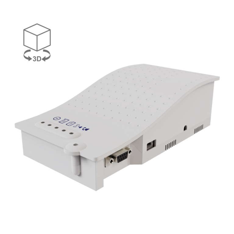
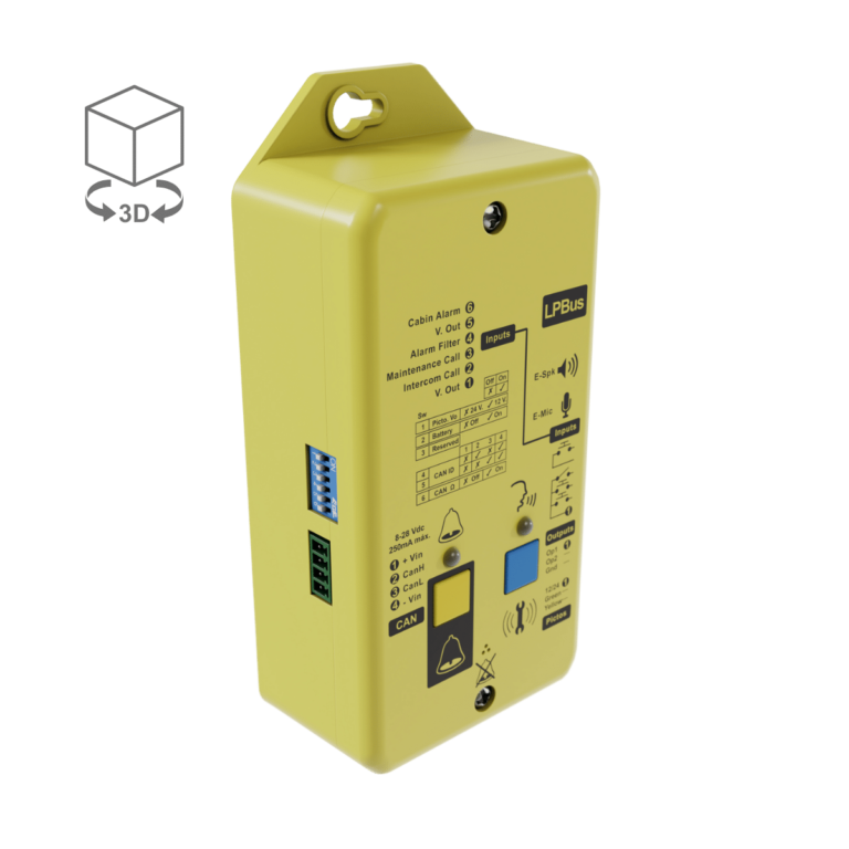
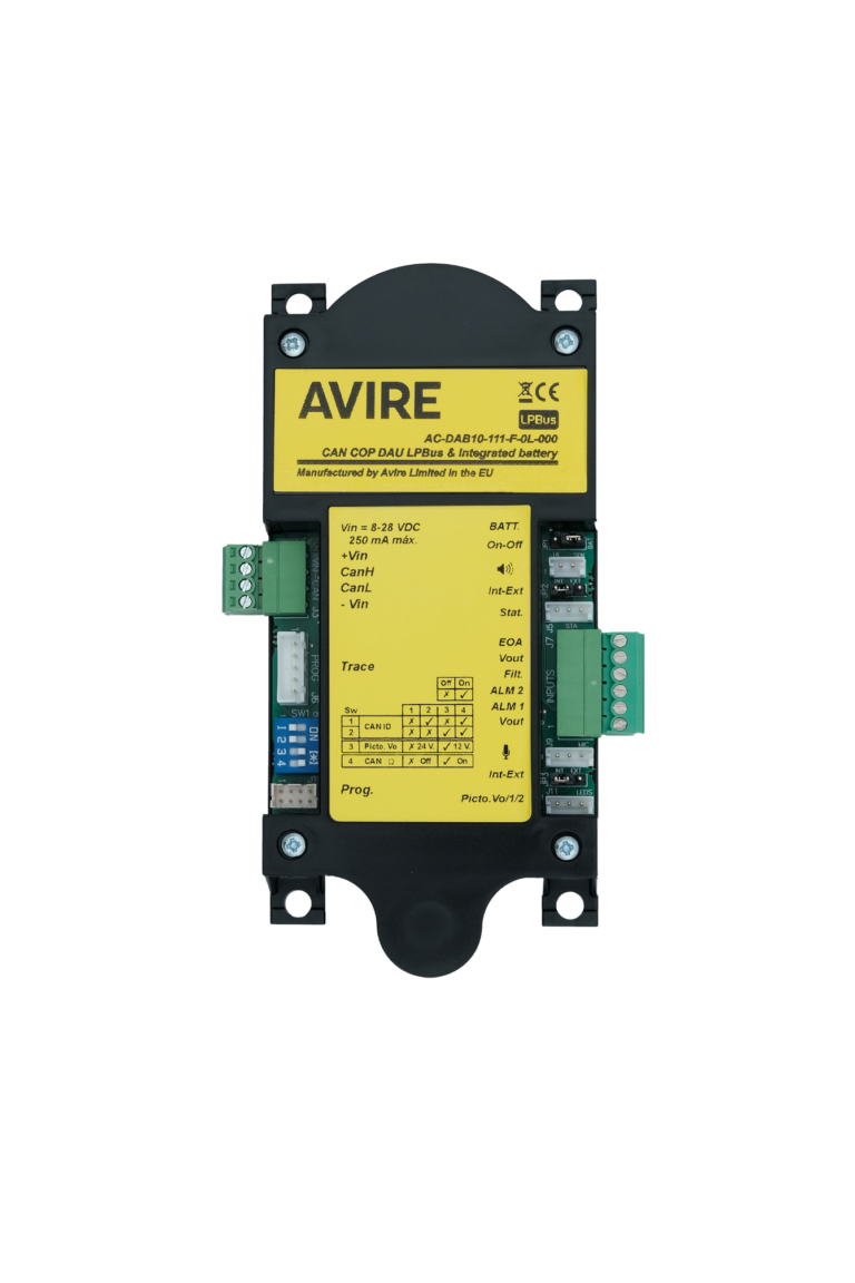
DCP Lift Digital Communication Platform
Bring your emergency telephone system into the digital age with the EN-81-28 compliant MEMCO Digital Communications Platform (DCP).
Memcom+ Lift Emergency Phone
The Memcom+ lift emergency phone is a high-quality, and reliable autodialler that provides trapped passengers quick and easy access to emergency assistance. The unit has a speaker, microphone, and backlit LCD for programming and status updates.
Universal Gateway
Upgrade an existing system, with up to four telephone units, from PSTN to GSM or install an EN81-28 compliant emergency lift phone system. Program telephone numbers directly into this easy-to-install GSM autodialler, with remote firmware update capability.

Accesories

AVIRE M2M Lift SIM Card
Stable and reliable, the AVIRE Machine to Machine (M2M) lift SIM cards connect automatically to any network provider to ensure the best signal, and won’t be disconnected due to low usage, keeping your lift communication system open at all times.
Memcom+ Accessories Multi Point Station MPS
For use during installation and commissioning, the lift Multi Point Station (MPS) provides emergency telephone points for the lift engineer in the shaft, pit, or machine room. The easy-to-install MPS has LED status lights and adjustable volume control.
Memcom+ Accessories Wiring Looms
Connect Memcom products quickly, easily, and error-free with pre-wired looms, each with a wiring harness and clearly labelled connections. The wiring looms are compatible with leading lift manufacturers and are pre-wired into the Memcom terminal block.
Memcom+ Accessories Inductive Loop
Ensure your lift complies with equal access legislation with an inductive loop that enables passengers with hearing aids to hear the response to emergency calls and operator instructions clearly.
Memcom+ Accessories Surface Mount COP
A sleek and modern speaker and microphone for emergency calls, this lift surface mount for the Car Operating Panel (COP) is quick and easy to install. With back-lit colour pictograms, emergency lighting, and anti-vandalism security screw.
Memcom+ Accessories Flush Mount COP
A range of lift emergency telephone products with speaker and microphone, for flush mount installation on the Car Operating Panel (COP). From simple units with LED indicators to premium stainless steel plates with pictograms and alarm push buttons.
DCP Accessories CAN Bus Splitter
The CAN Bus is the ‘nervous system’ of the lift network, acting as an intermediate between one Digital Communication Platform (DCP) and multiple Digital Audio Units. Connect up to four CAN Bus lines with the MEMCO CAN Bus splitter, to simplify multiple-shaft or single-shaft installation wiring. The CAN Bus Splitter contains five CAN terminating resistors and does not require a power supply.
DCP Accessories Universal Power Supply
The MEMCO Universal Power Supply is mounted in the motor room and provides both 12VDC power and battery backup to support an extended CAN Bus system for the Digital Communications Platform.
DCP Accessories Top of Car Digital Audio Unit
The MEMCO Top of Car Digital Audio Unit (TOC DAU), is a compact, affordable, and compliant emergency phone solution. It connects to the Digital Communications Platform (DCP), provides a TOC alarm point, an external speaker and microphone inside the lift car, and is ideal for lift groups.
DCP Accessories COP Digital Audio Unit
An elevator audio unit that provides high-quality digital audio when installed with the lift emergency Digital Communications Platform (DCP). Mounted behind the Car Operating Panel (COP), the slimline COP DAU also has an integrated battery backup.
DCP Accessories Wiring Looms
Part of the MEMCO Emergency Communication System. Loom wire for the Car Operating Panel Digital Audio Unit (COP DAU) as well as the Top of Car Digital Audio Unit (TOC DAU). Compatible with OEM.
DCP Accessories Pit Phone Digital Audio Unit
The MEMCO PIT Digital Audio Unit is a pit phone unit that is mounted in the pit of a lift shaft, to provide an emergency communication point when connected to the DCP. It has an emergency battery backup and a yellow casing for visibility.
DCP Accessories Surface Mounted Audio Module
The slimline MEMCO Surface Mounted Audio module is mounted on the Car Operating Panel (COP), with easy install connection to the Digital Audio Unit (DAU), providing high-quality digital audio.
DCP Accessories Triphony Unit
The Triphony Unit is a digital audio module, powered via digital audio units (DAU), that can be used with the Digital Communications Platform (DCP) for internal or external emergency lift communication. It can be installed on the top or bottom of the lift car.
DCP Accessories Inductive Loop
The MEMCO Inductive Loop transmits a clear audio signal directly into the hearing aid of hearing-impaired passengers, ensuring compliance with EN81-70. Can be fitted behind COP (even retroactively), with a LPBUS connection to the DAU.
DCP Accessories Lift HAWK
Remote lift monitoring reduces false and costly engineer callouts. The compact lift sensor monitors lift movements. To identify possible issues, the self-learning system identifies low-activity periods to autonomously perform tests.
DCP Accessories Connex-02
The Connex-02 is a remote lift control module that, with the DCP, provides lift monitoring via the AVIRE HUB. User-defined inputs and outputs enable monitoring of service or maintenance status, engineer on-site duration, door cycles, and more.
DCP Accessories Navigation Box
A smart sensor that provides insights into lift journeys. The lift Navigation Box helps building owners and maintenance providers make informed, data-driven decisions on the timing of essential maintenance to reduce malfunction and downtime.

Elevator Emergency Communication
standards

EN 81-28

ASME A17.1-2019 / CSA B44-19 Safety Code for Elevators and Escalators

ASME A17.1-2019 / CSA B44-19 ‘Safety Code for Elevators and Escalators

Section 2.13: Power Operation of Hoistway Doors and Car Doors

  • 2.13.5 Reopening Device(s) for Power-Operated Horizontally Sliding Doors and Gates
    Reopening device(s) for power-operated horizontally sliding doors or gates shall conform to the requirements of 2.13.5.1 through 2.13.5.6. Where the term “door(s)” is used, the requirement shall apply to “gate(s)” as well.
  • 2.13.5.1 Where Required and Function.
    Where required by 2.13.4, power-operated doors shall be provided with a reopening device(s) that operates as follows:
    • a) If an object has been detected in accordance with 2.13.5.3 or 2.13.5.4 when the doors are fully open, the hoistway door and car door shall not close or, when the doors are closing, the car door and hoistway door at the landing shall initiate a reversal without intentional delay beyond system response time, and shall fully reopen or reopen a minimum of 915 mm (36 in.).
    • b) If the doors fail to fully close [see 2.12.2.2(a)] within 10 s in addition to the door close data plate value, the doors shall fully reopen.
  • 2.13.5.2 Rendering Inoperative
    • a) The reopening device(s) shall be permitted to be rendered inoperative
      • 1) when the closing kinetic energy is reduced in accordance with 2.13.4.2.1(c)(1) and 2.13.4.2.1(c)(2)
      • 2) for detection of approaching objects
        • a) within 450 mm (18 in.) of the point at which the leading edge of the leading door panel contacts the door jamb or opposing door panel.
        • b) when 20 s have transpired after the detection means of approaching objects first detects an object. When an object is detected in the path of the doors, the 20 s duration shall reset.
      • 3) for detection of objects in the door path, within 20 mm (0.75 in.) of the point at which the leading edge of the leading door panel contacts the door jamb or opposing door panel
    • b) Where Phase I Emergency Recall Operation by a fire alarm initiating device (see 2.27.3.2) is not provided, door reopening devices that can be affected by smoke or flame shall be rendered inoperative after the doors have been held open for 20 s after a door close signal has been initiated. Door closing for power-operated doors shall conform to 2.13.4.
    • c) When the reopening device(s) has been rendered inoperative per (a)(1), a continuously sounding audible signal shall be provided with a sound level of 10 dBA minimum above ambient and shall not exceed 80 dBA. The sound level shall be measured 1 m 40 in.) above the landing floor, 500 mm (20 in.) from the door face, along the centerline of the entrance opening, with the doors open. The signal shall sound during door closing until the doors are fully closed. In no case shall the sound level exceed 85 dBA inside the cab and within 300 mm (12 in.) from the centerline of the entrance and 1 m (40 in.) above the floor.
  • 2.13.5.3 Detection of Approaching Objects.
    The reopening device(s) shall be designed to detect a cylindrical target(s) approaching the entrance opening of the landing-side doors as required by 2.13.5.3.1. The cylindrical target(s) shall be oriented with the base parallel to the floor, the height perpendicular to the floor, and properties conforming to the following:
    • a) diameter of 200 mm (8 in.), height of 1 000 mm (40 in.), and painted flat black per FED-STD-595C in the color range from 37005 through 37050 diameter of 200 mm (8 in.), height of 1 000 mm (40 in.), and painted glossy white per FED-STD-595C in the color range from 17800 through 17999 NOTE (2.13.5.3): See Nonmandatory Appendix S, Figure S-13.
  • 2.13.5.3.1 Each cylindrical target shall be moved toward the entrance, perpendicular to the plane of the landing door, at any speed up to 1 m/s (3 ft/s). The cylindrical target shall be detected while moving toward the entrance anywhere between 500 mm (20 in.) and 225 mm (9 in.) from the landing-side face of the hoistway door and 225 mm (9 in.) ahead of the leading edge (see Nonmandatory Appendix S, Figure S-16 for moving line of detection). The cylindrical target shall be permitted to be detected prior to the position defined above. The approaching object detection means shall be effective until the leading edge of the doors is within 450 mm (18 in.) of the fully closed position and shall be permitted to be effective up to the fully closed position.
  • 2.13.5.4 Detection of Objects in the Door Path.
    The reopening device(s) shall be designed to detect rectangular prisms positioned as required by 2.13.5.4.1 and 2.13.5.4.2 with properties conforming to the following:
    • a) 80 mm (3.15 in.) by 50 mm (2 in.) by 150 mm (6 in.), painted flat black per FED-STD-595C in the color range from 37005 through 37050
    • b) 80 mm (3.15 in.) by 50 mm (2 in.) by 150 mm (6 in.), painted glossy white per FED-STD-595C in the color range from 17800 through 17999 NOTE (2.13.5.4): See Nonmandatory Appendix S, Figures S-14 and S-15.
  • 2.13.5.4.1 The device(s) shall be designed to detect prisms positioned anywhere within the opening width of the entrance vertically between two horizontal planes located 25 mm (1 in.) and 1 525 mm (60 in.), respectively, above the floor and oriented with the 50 mm (2 in.) dimension parallel to the floor, the 150 mm (6 in.) dimension perpendicular to the door, and the 80 mm (3.15 in.) dimension perpendicular to the floor
    • a) wholly located between the vertical planes established by the landing-side face of the hoistway door and the car-side face of the car door or
    • b) centered between the two vertical planes described in (a) if the distance between the two planes is less than 150 mm (6 in.)
  • 2.13.5.4.2 The device(s) shall be designed to detect prisms positioned anywhere within the opening width of the entrance on the floor and oriented with the 80 mm (3.15 in.) dimension parallel to the floor, the 150 mm (6 in.) dimension perpendicular to the door, and the 50 mm (2 in.) dimension perpendicular to the floor
    • a) wholly located between the vertical planes established by the landing-side face of the hoistway door and the car-side face of the car door or
    • b) centered between the two planes if the distance between the two planes is less than 150 mm (6 in.)
  • 2.13.5.5 Self-Monitoring of Detection Means.
    The system shall be designed to be self-monitoring. After the door has reached its fully opened position and before door closing is initiated, the detection means shall be self-checked to verify the detection means is operational. If the self-check outcome is unsuccessful, power closing of the door(s) shall be at reduced kinetic energy conforming to 2.13.4.2.1(c)(2).

Section 2.27.1: Car Emergency Signaling Devices

  • 2.27.1 Car Emergency Signaling Devices
  • 2.27.1.1 Emergency Communications. The two-way communications shall conform to 2.27.1.1.1 through 2.27.1.1.6.
  • 2.27.1.1.1 A communications means between the car and a location staffed by authorized personnel who can take appropriate action shall be provided.
  • 2.27.1.1.2 If the call is not acknowledged [2.27.1.1.3(c)] within 45 s, the call shall be automatically directed to an alternate on- or off-site location.
  • 2.27.1.1.3 The communications means within the car shall comply with the following requirements:
    • (a) In jurisdictions enforcing the NBCC, Nonmandatory Appendix E; in jurisdictions not enforcing the NBCC, ANSI/ICC A117.1, ADAAG, or ADA/ABAAG.
    • (b) A push button to actuate the communications means shall be provided in or adjacent to a car operating panel. The push button shall be visible and permanently identified with the phone symbol (see 2.26.12.1). The identification shall be on or adjacent to the phone push button. The communications means shall be initiated when the push button is actuated.
    • (c) On the same panel as the phone push button, a message shall be displayed that is activated by authorized personnel to acknowledge that communications are established. The message shall be permitted to be extinguished where necessary to display a new message [see (d) and (e)] or when the communications are terminated.
    • (d) On the same panel as the phone push button, messages shall be displayed that permit authorized personnel to communicate with and obtain responses from a trapped passenger(s), including a passenger(s) who cannot verbally communicate or hear.
    • (e) On the same panel as the phone push button, a message shall be displayed that is activated by the authorized personnel to indicate when help is on the way. The message shall continue to be displayed until a new message is displayed [see 2.27.1.1.4(c)] or the communications are terminated.
    • (f) The communications means shall provide on demand to authorized personnel information that identifies the building location and elevator number.
    • (g) The communications, once established, shall be disconnected only when authorized personnel terminate the call or a timed termination occurs. A timed termination by the communications means in the elevator, with the ability to extend the call by authorized personnel, is permitted if voice notification is sent by the communications means to authorized personnel a minimum of 3 min after communication has been established. Upon notification, authorized personnel shall have the ability to extend the call; automatic disconnection shall be permitted if the means to extend are not enacted within 20 s of the voice notification.
    • (h) The communications means shall not use a handset in the car.
    • (i) The communications shall not be transmitted to an automated answering system. The call shall be answered by authorized personnel.
    • (j) Operating instructions shall be incorporated with or adjacent to the phone push button.
    • (k) A means to display video to observe passengers at any location on the car floor, to authorized personnel for entrapment assessment, shall be provided.
  • 2.27.1.1.4 Where the elevator rise is 18 m (60 ft) or more, a communications means within the building accessible to emergency personnel shall be provided and shall comply with the following requirements:
    • (a) The means shall enable emergency personnel within the building to establish communications to each car individually. The communications shall be established without any intentional delay and shall not require intervention by a person within the car. The means shall override voice communications to outside of the building.
    • (b) The communications, once established, shall be disconnected only when emergency personnel terminate the call or a timed termination occurs. A timed termination by the communications means in the elevator, with the ability to extend the call by emergency personnel, is permitted if voice notification is sent by the communications means to emergency personnel a minimum of 3 min after communication has been established. Upon notification, emergency personnel shall have the ability to extend the call; automatic disconnection shall be permitted if the means to extend are not enacted within 20 s of the voice notification.
    • (c) Once the communications have been established, a message shall be displayed on the same panel as the phone push button, that is activated by emergency personnel to indicate that help is on-site. The message shall be permitted to be extinguished where necessary to display a new message [see (e)] or when the communications are terminated.
    • (d) Operating instructions shall be incorporated with or adjacent to the communications means outside the car. Instructions shall conform to 2.27.7.3.
    • (e) On the same panel as the phone push button, messages shall be displayed that permit emergency personnel to communicate with and obtain responses from a trapped passenger, including a passenger who cannot verbally communicate or hear.
    • (f) A means to display video to observe passengers at any location on the car floor, to emergency personnel for entrapment assessment, shall be provided.
  • 2.27.1.1.5 If the communications means is connected to the normal building power, it shall automatically transfer to an auxiliary power supply as required by the applicable building code or, where applicable, NFPA 99, after the normal building power fails. This power source(s) shall be capable of providing for the means of communications (see 2.27.1.1.3 a n d 2.27.1.1.4) for at least 4h and the audible signaling device (see 2.27.1.2) for at least 1h.
  • 2.27.1.1.6
    • (a) The voice communication means within the car shall include a means to verify operability of the telephone line, where
      • (1) verification of the telephone line operability shall be automatically performed
      • (2) verification may be continuous or periodic
      • (3) periodic verification shall be at least on a daily basis
      • (4) verification shall not require activation of the communications link(s) If means other than a telephone line (e.g., VOIP, network, intercom) are used for the communications, similar verification of this equivalent means shall be performed.
  • 2.27.1.2 Emergency Stop Switch Audible Signal.
    When an emergency stop switch (2.26.2.5) is provided, an audible signaling device shall be provided. The audible signaling device shall:
    • (a) have a rated sound pressure rating of not less than 80 dBA nor greater than 90 dBA at 3 m (10 ft)
    • (b) respond without delay after the switch has been activated
    • (c) be located inside the building and audible inside the car and outside the hoistway
    • (d) for elevators with a rise greater than 30 m (100 ft), be duplicated as follows:
      • (1) one device shall be mounted on the car
      • (2) a second device shall be placed at the designated level

EN 81-28

The EN 81-20 safety standards are part of building regulations that set out lift requirements for passenger and goods lifts. We review the minimum safety standards for lift emergency telephones in the UK. 

Why was EN 81-20 needed to regulate lift safety requirements? 

The lift safety standard was introduced to increase safety due to changes in proven technology and bring the requirements in line with modified EU directives. It also eliminated the separate standards for hydraulic lifts and introduced the requirement for risk analysis and compliance. 

Some of the issues the new standard aimed to address include increased strength of doors, car, and well, improved lighting in the lift car, stopping people being able to exit the car if it stopped between floors, improved materials such as flameproof materials and safety glass, increased refuge space, increased refugee space in the pit and more headroom, and improvements to the lift emergency telephones to ensure passengers are able to summon help in the event of a breakdown.  

EN 81-20 lift safety requirements  

The EN 81-20 safety requirements were introduced in 2017 and apply to all new lifts. They cover all aspects of lift safety, including lighting, material strength, flameproofing, and refuge space.  

The EN 81 series covers different aspects of lift safety. EN 81-20 is the overarching standard, covering safety rules for the construction and installation of lifts that transport people and goods. The rest of the EN 81 series covers specific safety measures, such as the standards for lift light curtains (EN 81-20) and accessibility standards, including for persons with a disability (EN 81-70).  

The regulations that set standards for lift emergency telephones are contained in EN 81-28, introduced in 2003, and updated in 2018. 

What are the EN 81-28 standards for lift emergency telephones? 

The EN 81-28 standards regulate the remote alarm system for passenger and goods lifts. Sometimes known as emergency telephones, autodiallers, tele-alarms, or lift phones, these systems enable passengers to summon assistance if they are trapped in a lift due to a fault. 

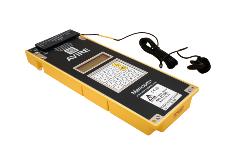
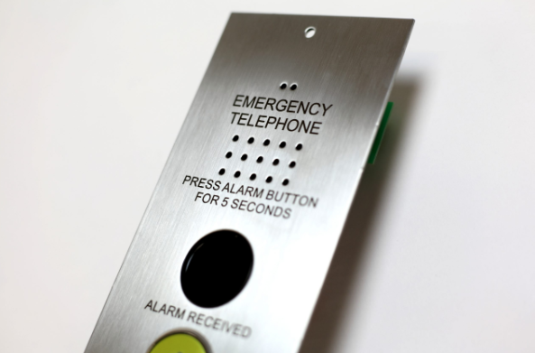
Lift emergency telephone for passengers and engineers  

To stay compliant with EN 81-28, the lift emergency phone must be available to anyone trapped. In addition to lift passengers, this also applies to lift engineers when they are on the top of the car, in the pit (the base of the lift shaft underneath the lift), or in the lift motor room, depending on the lift motor room access. 

Lift emergency telephone battery requirements  

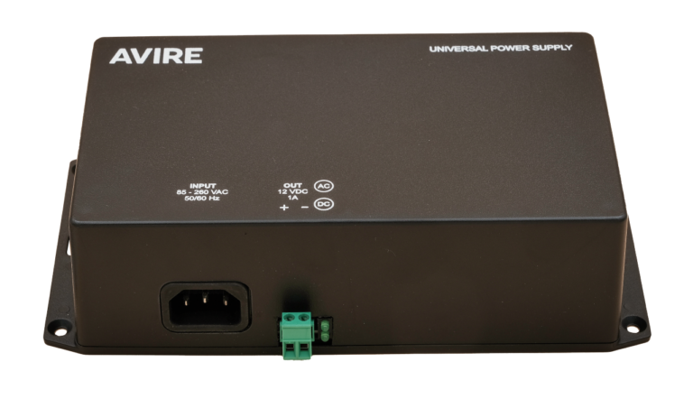
The lift safety standards mandate that emergency communications equipment have sufficient power backup to last one hour on standby, with a minimum of 15 minutes of talk time, in the event of a power failure. In the interest of passenger safety, AVIRE recommends doubling the talk time.  

Lift emergency telephone 3-day test calls  

A test call must be made every three days to ensure the lift alarm system is working properly, proactively identify and fix faults, and reduce the risk of malfunctions. 

The test call is initiated using the alarm equipment in the lift, which dials into a receiver – generally a software platform – that records the test call. During this call, the emergency lift telephone will provide information on the speaker, microphone, and battery status. A record of the test call is kept to show compliance with regulations, and that all required steps were taken to ensure passenger safety. This record may be required in the event of a lawsuit.  

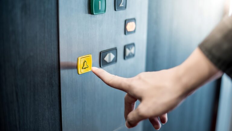
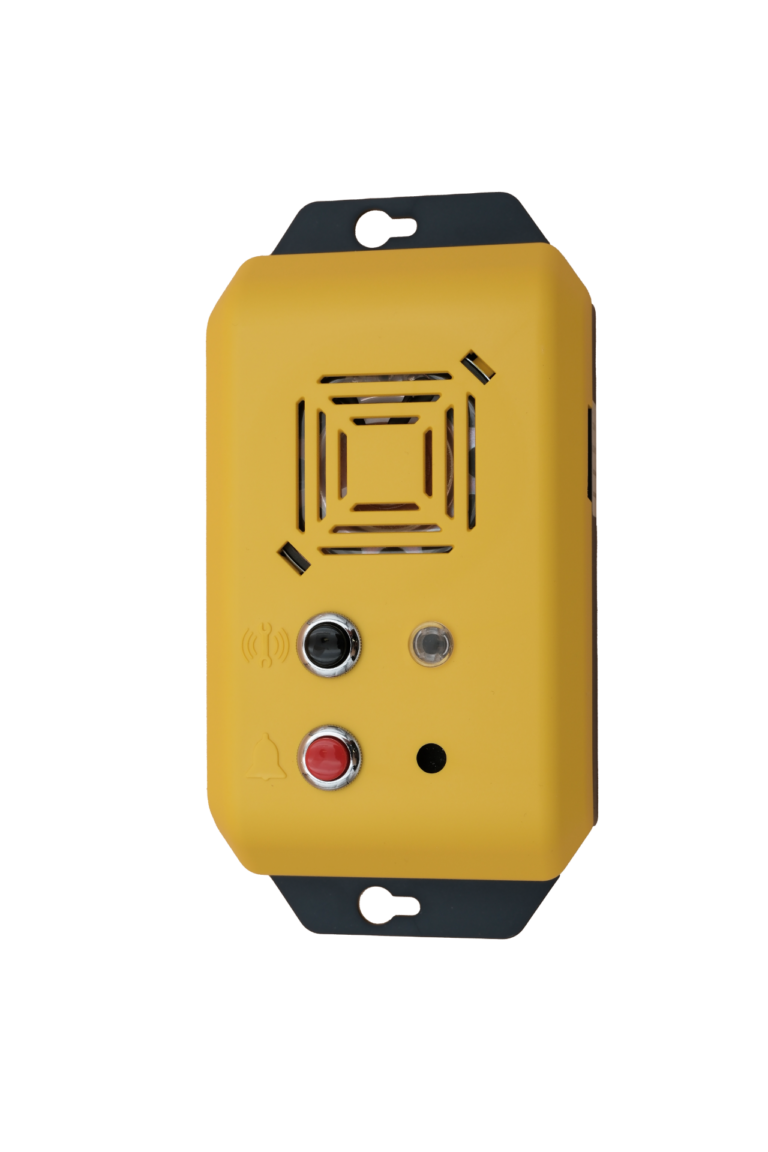
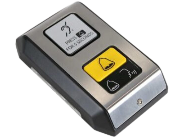
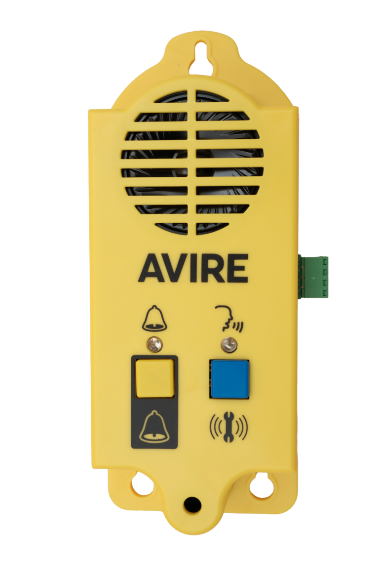
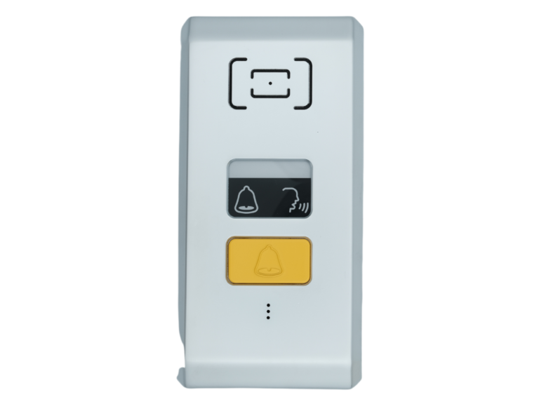
Pictograms for hearing-impaired passengers  

Illuminated symbols enable hearing-impaired passengers to understand the status of their alarm call. When the alarm button is pressed, the yellow pictogram signals that the lift emergency system is placing a call. The yellow pictogram stays on once the alarm has been answered, and a green pictogram of a person speaking is shown. 

The green light goes off when the voice call is over. The yellow light stays on until the end of the alarm signal is sent back to the emergency phone, signalling the trapping has been dealt with.  

Lift emergency telephone standby and alarm status – protecting passenger privacy 

Pressing the alarm button puts the alarm equipment from standby into alarm status. During this time, the rescue company can dial in and speak to the trapped passengers in the lift. 

When the entrapment is over, and the passengers are freed, the emergency telephone system must be put back into standby status to prevent someone from calling into the lift car and listening to passenger conversations. The yellow bell pictogram signals to passengers that the alarm is still active, and third parties can hear their conversations.  

Flashing pictograms indicate a fault in the lift emergency telephone system 

If a 3-day test call fails, EN-81 28 regulations stipulate that the pictograms must flash to signal to lift users that there is a problem with the emergency alert system – either the hardware or the connection to the rescue company. The lights will continue flashing until the next successful test call is completed. 

The EN 81-20 lift standards and requirements for lift emergency telephones in older lifts  

While the EN 81-20 lift standards do not apply to older lifts, the industry has adopted these safety standards to increase safety and reduce lift damage. Property owners who upgrade their lift safety systems to meet the new requirements will increase the value of their property while increasing passenger safety.  

How to ensure your building meets EN 81-28 lift safety requirements 

It can be challenging to keep track of changes to lift safety requirements. That’s why our mechanics and engineers are trained comprehensively on all safety standards and can help plan lifts for a new property or upgrade existing lifts to be fully compliant with EN 81-28. 

Going beyond the minimum safety requirements of EN 81-20 

All MEMCO products comply with EN 81-20 regulations, and many of our solutions go well beyond the minimum safety requirements. 

For example, the leading cause of lift failure is door damage caused by someone inserting an object between the doors to stop them from closing. A more advanced lift light curtain can alert the lift owner to obstructions or damage that may cause non-compliance with lift safety legislation. 

Digital lift monitoring solutions via the AVIRE Hub make it easy to comply with monitoring requirements and the 3-day test calls. 

Contact us


I consent to my details being stored in reference to the GDPR. See Privacy Policy


What is CANBus?
What is an M2M SIM Card for lifts?
Top Tips for Lift Autodialler Installations
Time for a lift modernisation? How to convince your manager!